Followers

Showing posts with label Technology. Show all posts

Wednesday, June 12, 2024

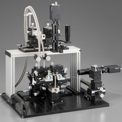
The features typically found in an optical fiber alignment system

An optical fiber alignment system is a device or setup used to precisely align optical fibers for efficient coupling of light between them. These systems are crucial in various applications where accurate alignment is essential, such as in telecommunications, fiber optic sensing, laser systems, and optical instrumentation.

Here are some key components and features typically found in optical fiber alignment systems:

1.      Fiber Holders: These are fixtures or clamps designed to securely hold optical fibers during alignment. They may include features such as adjustable grips or V-grooves to accommodate different fiber diameters and types.

2.      Alignment Stages: Alignment stages provide controlled movement in multiple axes to adjust the position of the fibers with high precision. These stages may use manual adjustment screws, micrometer drives, or motorized actuators for fine-tuning the alignment.

3.      Alignment Visualization: Optical fiber alignment system often includes visualization tools to aid in the alignment process. This may involve using cameras, microscopes, or alignment lasers to monitor the position and alignment of the fibers in real-time.

4.      Feedback Mechanisms: Some advanced alignment systems incorporate feedback mechanisms to automatically adjust the fiber positions based on real-time measurements of optical power or other relevant parameters. This can streamline the alignment process and improve accuracy.

5.      Software Control: In automated alignment systems, software control allows users to define alignment parameters, set target positions, and initiate alignment sequences. This enables efficient and repeatable alignment processes, particularly in high-volume manufacturing environments.

6.      Environmental Control: Optical fiber alignment systems may include features to mitigate environmental factors that could affect alignment accuracy, such as temperature fluctuations or vibration. This can involve enclosing the alignment setup in a controlled environment or using vibration isolation techniques.

Optical fiber alignment system comes in various configurations and complexities, ranging from simple manual setups to fully automated alignment stations with advanced feedback control. The choice of system depends on factors such as alignment accuracy requirements, throughput, and budget constraints.

The Fiber Fused Biconical Taper (FBT) Systems Potential


In the complicated network of fiber optic transmission, FBT systems are the pinnacle of precision engineering. FBT Fiber Taper Machine provides seamless light coupling and signal transport by combining several optical fibers into a single, tapered structure, establishing a new standard for optical networking efficiency and dependability.

Enhancing Telecommunications Infrastructure

FBT systems contribute significantly to the improvement of telecommunications infrastructure. These methods provide optical communication integrity over long distances by reducing signal loss and reflection. Whether splitting signals for distribution or combining them for amplification, FBT systems provide a dependable choice for high-speed data transport in telecommunication networks.

Precision in optical networking

In the world of optical networking, precision is critical. Fiber fuse biconic taper machines offer unparalleled control over light propagation, making them perfect for wavelength division multiplexing and power monitoring applications. Their tiny size and low insertion loss make them ideal for use in optical switches, routers, and other networking devices, allowing for seamless data transfer across several networks.

Diverse Applications Beyond Telecommunications

While Fiber Fuse Biconic Taper Machine thrives in telecommunications, its benefits are far-reaching. These systems have applications in sensing technologies, where their precise control over light enables accurate measurements of a variety of variables such as temperature, pressure, and strain. FBT systems provide a flexible solution for a wide range of sensing applications, including environmental monitoring and industrial automation.

Their durability, versatility, and precise light control capabilities make them indispensable in a wide range of applications, shaping the future of fiber optics technology. With ongoing research and adaptation, FBT technologies are poised to accelerate progress and revolutionize how we communicate and interact with the environment.

Bring on the fiber cable stripper!

Accuracy and uniformity: These machines use sophisticated sensors and accurate blades to strip wires consistently and precisely, reducing the chance of fiber breakage.

Efficiency: By automating the stripping process, these devices considerably cut labor costs while enhancing efficiency, resulting in quicker fiber optic network development and higher throughput.

Safety: These machines reduce the danger of harm from manual cable stripping by providing a safe working environment for users thanks to built-in safety safeguards and protections.


Modern FBT Fiber Taper Machine are simple to use and need little training, so personnel may rapidly become proficient with the equipment and complete tasks with ease.

Follow our Facebook Facebook and Twitter Twitter for more information about our product.

Wednesday, March 20, 2024

The Role of Fiber Crimping and Curing Oven Machine


Data transfer at lightning rates is now a need in the world of modern technology, not a luxury. The sophisticated procedures that guarantee the effectiveness and dependability of fiber optic cables are at the core of this technical wonder. Two essential elements of these procedures are the Fiber Crimping Machine and the Fiber Curing Oven.

Fiber Curing Oven

Optimizing Sturdiness and Dependability: Because they are fragile materials, fiber optics must be handled carefully to preserve both their performance and integrity. The Fiber Curing Oven comes into play here. It is essential to the manufacturing process because it strengthens and increases the mechanical strength of the optical fibers by curing them.

Curing Procedure: The fiber optic cables must be exposed to regulated heat during the curing process, usually in a Fiber Curing Oven. The cables' polymer matrix experiences cross-linking reactions as a result of this heat treatment, improving their mechanical qualities.

Mechanical Strength: The Fiber Curing Oven greatly increases the tensile strength of the fibers by curing them, enabling them to endure the rigors of installation and use without sacrificing performance.

Reliability: Over extended periods, reliable data transmission is ensured by cured fibers' decreased vulnerability to environmental elements including moisture and temperature variations.

Quality Control: The Fiber Curing Oven is an essential component of quality control, guaranteeing that every fiber optic cable satisfies strict industry requirements for dependability and longevity.

Fiber Crimping Machine

Fine Precision in Connectivity: Precision and accuracy are necessary while connecting fiber optic cables to preserve signal integrity and reduce losses. This is where fiber optic cable termination and splicing are made simple with the help of the Fiber Crimping Machine.

Exact Termination: With the help of the Fiber Crimping Machine, fiber optic connector termination may be done precisely, guaranteeing ideal alignment and little signal loss during data transfer.

Beyond termination, the Fiber Crimping Machine's splicing capabilities enable the smooth connecting of fibers to increase network coverage or fix damaged areas.

Efficiency: These devices greatly increase production by automating the crimping process, which lowers labor expenses and speeds up fiber optic installations and maintenance.


Uniformity: By guaranteeing uniformity in splices and terminations, the Fiber Crimping Machine reduces variability and guarantees consistent performance across all connections.

Tuesday, March 19, 2024

Know About The Fiber Cable Cutting and FBT Fiber Taper Machine

The foundation of connectivity in the quickly developing field of telecommunications, where dependability is crucial and data transmission speeds are constantly rising, is found in the complex field of fiber optics. The intricately designed FBT Fiber Taper Machine and Fiber Cable Cutting Machine are essential tools for molding and optimizing fiber optic cable performance.


The Fiber Optics Revolution

Fiber optics has completely changed communication networks all over the world by enabling data to be sent over great distances at the speed of light. The optical fibers, which are pliable, thin strands of plastic or glass that transmit data as light pulses, are the central component of this technology. The need for dependable and effective fiber optic components is growing as demands for higher internet speeds, high-definition video streaming, and strong communication networks rise.

Accurate Engineering Precision: The Machine for FBT Fiber Taping

The FBT Fiber Taper Machine, a high-precision tool that can tape optical fibers with unmatched accuracy, is the center of fiber optic production. For optimum performance, fiber Bragg gratings, couplers, and other crucial parts need to be precisely tapered. This is accomplished by the FBT Fiber Taper Machine by precisely regulating the fiber's stretching and heating, which results in consistent taper profiles and little insertion loss.

The adaptability of the FBT Fiber Taper Machine is one of its key features. It is essential for many different applications since it can handle several types of fibers, such as polarization-maintaining, multimode, and single-mode fibers. The FBT Fiber Taper Machine meets the industry's strict requirements by producing consistent and dependable results for laser, sensor, and telecommunications applications.

Increasing Productivity: The Fiber Cable Cutting Device

To manufacture high-quality components, fiber optic cables must be precisely cut in addition to being tapered. The Fiber Cable Cutting Machine is useful in this situation. These machines minimize fiber end-face imperfections and reduce signal attenuation by ensuring clean and accurate cuts through the use of modern cutting mechanisms like laser or diamond blades.


The Fiber Cable Cutting Machine is incredibly efficient and can handle many fibers at once with a high throughput. These devices cut ribbon cables and individual fibers with remarkable speed and accuracy, producing reliable results every time. 

Follow our Facebook and Twitter for more information about our product.

Monday, January 22, 2024

A Deep Dive into Fiber Curing Ovens, Polishing Films, and Crimping Machines


With the introduction of fiber optics, the world of data transport and telecommunications has experienced a significant shift. These microscopic glass or plastic fibers carry information at light speed, allowing for high-speed internet access, crystal-clear phone conversations, and quick information sharing. The efficiency and quality of these optical fibers are guaranteed by complex manufacturing procedures that take place in the background. 

Ovens for Curing Fiber

A rigorous curing procedure is used for fiber optic cables to guarantee maximum strength and longevity. Fiber Curing Oven is essential for this stage. These ovens offer a regulated setting for the polymerization of the epoxy resin coating on the fibers, producing a strong and durable protective layer.

Precise temperature control, consistent heating, and programmed curing cycles are the main characteristics of fiber-curing ovens. To produce fiber optics consistently, several elements are necessary. The mechanical and thermal characteristics of the fibers are directly impacted by the curing process' effectiveness, guaranteeing that they can resist the demands of practical uses.

Films for Polishing Fibers

To provide the required optical clarity, the fibers are polished once they have been cured. In this phase, Fiber Polishing Films are essential. These films offer a controlled abrasive surface for refining the end faces of the optical fibers. They are commonly composed of diamond particles contained in a resin matrix.

To reduce signal loss and increase the efficiency of light transmission, the accuracy of Fiber Polishing Film is essential. Because the films are available in several grit sizes, producers can fulfill industry requirements and obtain the appropriate surface quality. The outcome is a polished fiber end face that enables efficient light coupling and eliminates reflections, adding to the overall performance of the fiber optic system.

Machines for Crimping Fiber

Compressing a metal sleeve onto a fiber optic connection to ensure its secure attachment is known as crimping. By automating this vital process, the Fiber Crimping Machine provides uniformity and accuracy in the manufacturing of fiber optic connections. A strong connection that can resist mechanical stress and environmental variables is ensured by good crimping.


Follow our Facebook and Twitter for more information about our product.

Saturday, August 12, 2023

A Glimpse into Precision Optics with Wonders of Fiber Identifier

A fiber interferometer is an optical device created to make use of light's wave-like properties for accurate measurements. It works by combining two or more light waves to produce a resultant wave that carries data about their relative phases. This process is known as the interference principle.


Important Elements and Operating Principles

The optical fibers at the center of a fiber interferometer transmit light across great distances with little loss. The fundamental arrangement is utilizing a beam splitter to divide a single light beam into two directions. Before coming back together at a detector, these pathways pass via several fiber arms. An interference pattern, often known as a pattern of alternately light and dark fringes, is produced by the interference between the two beams. The Fiber Interferometer can detect even the smallest changes in the physical values being measured by analyzing variations in this pattern. You can buy visual fault locator online.

Applications in a Wide Range of Fields

  • Metrology and Accurate Measuring: In metrology labs and the industrial sector, fiber interferometers are widely used for accurate length measuring, surface profiling, and alignment. They are essential instruments for quality assurance and calibration procedures because of their excellent precision and stability.
  • Environmental Sensing: To identify minute variations in temperature, pressure, and refractive index, these instruments are used in environmental monitoring systems. They help us comprehend the dynamics of the oceans, the atmosphere, and the geological processes on Earth.
  • Characterization of Materials: Researchers use Fiber Interferometers to examine the mechanical and thermal characteristics of materials, assisting in the development of innovative materials for the electronics, aerospace, and automotive sectors.
  • Detection of Gravitational Waves: In the field of astrophysics, Fiber Interferometers are a vital component of complex systems, which made significant gravitational wave discoveries that supported Einstein's general theory of relativity and opened up new research directions.


Outlooks for the Future

Fiber interferometers and fiber identifier have a remarkably bright future. More sensitive and compact interferometers are being created as a result of developments in nanotechnology and materials science. They are being improved to increase their performance and reliability for a wider variety of applications. Fiber Interferometers may play a crucial role in quantum computing, secure communication, and other cutting-edge industries as technology advances.

Friday, June 16, 2023

Demystifying the Optical Power Meter: Unveiling the Secrets of Light Measurement

Specialized equipment used to measure the strength of light signals in optical fibers is known as an optical power meter. Optical power meter measures optical power quantitatively in quantities such as watts (W) or decibels (dBm), providing vital insights into the performance and health of optical networks.


Operation and components:

Optical power meters are made up of a photodetector, which transforms light into electrical signals, and a display unit, which displays the measured power. The wavelength range of the light signals to be monitored determines the photodetector, which is often a silicon or indium gallium arsenide diode.

Optical power meters can measure wavelengths ranging from visible light to infrared, encompassing the most widely used wavelengths in fiber optic communication systems. Some sophisticated versions additionally have replaceable detectors, which allow users to adapt to varied wavelength ranges.


Optical Power Meter Applications:

Installation and upkeep: Optical power meters are essential during the installation and maintenance of fiber optic networks for evaluating signal strength, assuring proper splicing and connectorization, and resolving network faults. They assist technicians in identifying power losses or abnormal power levels, allowing them to take remedial action as soon as possible. Optical light source is also of great use.


Network Monitoring: In live optical networks, continual monitoring of optical power levels is required to identify signal deterioration, fiber breakage, and other abnormalities that might influence overall network performance. Optical power meters monitor power in real-time, assisting network operators in identifying possible faults and taking proactive actions to ensure network integrity.


Choosing an Optical Power Meter:

Several considerations should be addressed while choosing an optical power meter:


Power Measurement Range: Choose a power meter that can manage a wide range of power levels, accommodating both high and low power signals seen in various fiber optic systems.


Accuracy and Resolution: To guarantee exact measurements, look for a power meter with good accuracy and resolution. The resolution of an instrument defines the lowest observable power change, whereas accuracy represents its overall dependability.


Features and connectivity: Consider the power meter's connectivity choices, such as USB, Bluetooth, or Wi-Fi, which can help with data transmission and remote control. Data logging, wavelength identification, and auto-calibration are all features that can improve usability. You can buy fiber identifier online.

Sunday, May 14, 2023

Fiber Cable Cutting Machine: A Game-Changer in the Telecommunications Industry

Cutting, stripping, and splicing fiber optic cables all need the use of specialized equipment known as fiber cable cutting machines. To ensure that the fiber optic cable is cut neatly and precisely without harming the fragile fibers within, the machine employs a powerful laser to make the cuts.


Fiber cable cutting machine benefits

Compared to conventional cable-cutting techniques, using a fiber cable-cutting machine has several benefits. These consist of:

  • Precision: A fiber cable-cutting machine employs a laser to create exact cuts, guaranteeing that the cable is cut correctly and without causing any harm to the inside fibers. When working with fiber optic wires, which are sensitive to even minor damage, this accuracy is essential.
  • Speed: Compared to conventional cable-cutting techniques, fiber cable-cutting machines are substantially quicker, enabling workers to work more productively and finish operations more rapidly. This is crucial in circumstances when downtime must be reduced to a minimum.
  • Versatility: Fiber cable cutting machines are useful tools in the telecommunications sector because they can be used to cut and strip a range of various types of fiber optic cables. This eliminates the need for various tools and pieces of equipment since technicians may do multiple jobs on the same machine.
  • Safety: A fiber cable cutting machine is developed with safety elements that guard operators against the powerful laser that is used to create the cuts.


Fiber cable-cutting machine applications

Numerous applications in the telecommunications sector employ fiber cable-cutting equipment. Some of the most popular apps are as follows:

Fiber optic cables are cut and spliced using fiber cable-cutting equipment during maintenance and repair operations. This makes it possible for personnel to swiftly and effectively repair broken cables and maintain networks.

  • Fiber optic cables are cut and stripped using fiber cable-cutting equipment throughout the production process. This helps to preserve the end product's quality and guarantees that the wires are cut precisely and neatly.


Research and Development: Engineers may experiment with various fiber optic cable types and evaluate how they operate in various scenarios thanks to the usage of fiber cable cutting machines in research and development projects.

Friday, April 14, 2023

The Benefits and Limitations of Machine Learning in Business

For personnel working with fiber optic lines, fiber id is a crucial piece of equipment. Without interfering with the signal flow, they enable specialists to identify the type of fiber, ascertain the fiber's orientation, and detect the existence of signals on a fiber.


fiber identifier is a portable tool that enables technicians to recognize the kind of fiber, determine its orientation, and find signals on a fiber without halting the signal flow. Fiber identifiers function by detecting the light signal that is traveling through the fiber and reporting data on the signal's wavelength and intensity.

How Do Fiber Identifiers Function?

Fiber identifiers operate by detecting the light signal traveling through the fiber using a non-destructive method. Throughout the identification procedure, the fiber is not harmed, and neither is the signal. The fiber identifier's main working concept is clamping the fiber under test between two jaws so that it may identify the presence of a signal without cutting the fiber.

Some of the light that travels through a fiber is lost due to absorption or scattering. The kind of fiber, its length, and any other attenuation elements in the system all affect how much light is lost. The technician can ascertain the existence and strength of a signal thanks to the fiber identifier's and Visual Fault Locator’s detection of light signals and measurement of light intensity.

Fiber Identifiers' Value

While dealing with fiber optic connections, technicians need fiber IDs as a basic tool. These can aid in determining the type of fiber included in a cable, enabling personnel to choose the proper tools for installation or maintenance. Also, they enable technicians to establish the fiber's orientation, which is crucial for splicing or terminating fibers.

Very helpful for debugging fiber optic networks are fiber IDs. They enable technicians to pinpoint the site of a malfunction or signal loss since they can detect the existence of signals on a fiber without obstructing the signal flow. This is crucial for long-haul fiber optic networks since it might be difficult and time-consuming to locate defects there.


Fiber identifiers and Fiber Interferometer can also assist in avoiding damage to the fiber during setup or maintenance. Technicians can prevent mistakenly cutting or injuring fibers, which might cause downtime or expensive repairs, by detecting the presence of signals on the fiber.

Follow our Facebook and Twitter for more information about our product.

Monday, March 13, 2023

Get to Know About Polishing Fixtures Care

The polishing procedure using fiber polisher is arguably the most important stage in the construction of fiber optic cables to ensure high-quality assemblies that adhere to standards. Because of this, it's crucial to choose the optical fiber polishing equipment and polishing fixtures that are appropriate for your demands. You may have several polishing fixtures to create various connection types, depending on the product offers of your cable assembly business.


For your business, the polishing fixtures' quality—also known as the polishing plates or jigs' quality—is crucial. Your business will want to maintain these tools to create a high number of items with few quality concerns over the long term, given the high cost of manufacturing equipment and components.

Polishing equipment must be properly maintained.


High-precision machining tools are used to construct the fiber polishing fixture for optical fiber polishing machines. Steel and aluminum fixtures tend to bend and warp with time, which will affect your polishing procedure and the quality of your finished product. On the other hand, polishing equipment composed of stainless steel that has been hardened prevents this wear effect. Hardened stainless steel does increase the danger of corrosion, though, because there is more iron in the alloy. This is a major factor in why regular maintenance is so important.


Moreover, a plastic latch or clamp used to secure the three most popular fiber optic connections to the polishing fixture might deteriorate over time if not kept clean. Moreover, improper cleaning procedures might inhibit proper locking. This may have a considerable effect on the polishing machine's performance and, therefore, product quality. Your business will want to maintain these tools to create a high number of items with few quality concerns over the long term, given the high cost of manufacturing equipment and components.


As was already said, polishing may be the phase that makes or breaks high-quality fiber optic cable assemblies. We believe that following these upkeep and cleaning instructions along with a fiber polishing machine will enable you to make better use of these indispensable instruments and prevent quality issues and quick depreciation of this pricey equipment.

Saturday, February 11, 2023

Know About the Advanced Optical Power meter functions


Lab equipment must be ever more powerful, with more functions crammed into a single box, as well as inexpensive, to accommodate increasingly complicated experiments, safety, and environmental regulations, and push for greater performance at lower costs. Modern, state-of-the-art meters can handle much more than merely measuring optical power, and optical power meter is no exception. These meters may be used for a variety of tasks, including frequency measurement, multiple display and charting choices, statistical data, data gathering, easy mathematical operations, and decreased energy use.


With the use of detectors like photodiodes, thermopiles, or pyroelectric detectors, optical power meters may measure photon energy as current or voltage. The (detector) interface, the analog board, and the digital board are the three main parts that can be taken into account.


The overall functioning of power meters has undergone several significant changes. If the filtering function is accessible, it may be one of the most frequently utilized functions. To eliminate any undesired variations from the readings, users frequently prefer to apply a filter to the output reading. Some items come with a digital averaging feature or an analog low-pass filter circuit. The cutting-edge optical power meters include four levels of analog and digital filters, offering 256 potential filtering configurations. The optical light source is of great use.


The use of software approaches to compensate for the sluggish thermopile detector rise time is also noteworthy. Depending on the design and the heat absorption materials, the rise and fall periods of thermopile detectors range from 1 to 10 seconds. The traditional architecture physically accelerates the detector's reaction time via electronics. A trimming potentiometer, often known as a trim-pot, is typically set to obtain the signal's fastest rising time without producing a substantial overshoot or oscillation. Each type of thermal detector has a unique optimum value.


Finally, it's important to pay attention to the competition to cut manufacturing's use of electricity. The use of "green" manufacturing techniques is widely acknowledged across many industries.


The most recent optical power meters are now offered with a sleep mode, akin to that on a laptop, for power savings when the instrument is not in use and to save the warm-up period before first usage at the beginning of the day. You can buy fiber identifier online.

Friday, January 13, 2023

Working of a Fiber Optic Fusion Splicers

A fiber optic fusion splicer 

fiber splicer is a tool that joins two optical fibers at their end faces using an electric arc to create a single long fiber. The resultant junction, also known as a fusion splice, permanently unites the two glass fibers end to end, allowing optical light signals to move with negligible loss from one fiber to the other.


The way a fusion splicer functions

Optical fibers need to be meticulously cleaned, freed of their outer jackets and polymer coatings, and then properly split to create smooth, perpendicular end faces before they can be effectively fused. Each fiber is then put into a holder in the splicer's enclosure once all of this has been done. The remaining parts of the procedure, which entail three processes, are then handled by the fiber optic fusion splicer.


Alignment: To ensure that the resulting splice is as smooth and attenuation-free as possible, the fusion splicer makes minute modifications to the locations of the fibers until they are perfectly aligned. The optical power meter, video camera, or viewing scope's magnification allows the fiber optic technician to see the alignment of the fibers while they are being aligned. You can strip the cable using fiber stripper.


Impurity Burn-Off: When it comes to fusion splicing, you can never be too clean since even a small amount of dust or other impurities can seriously impair a splice's capacity to transfer optical information. Many fusion splicers include an additional precautionary cleaning step in the process even if fibers are manually cleaned before being introduced into the splicing device. This step involves generating a little spark between the fiber ends before fusing to burn off any lingering dust or moisture.


Fusion: The ends of the fibers should be fused to produce a permanent splice once they have been appropriately positioned and any leftover moisture and dust have been burnt out. A second, bigger spark from the splicer melts the ends of the optical fibers without causing the cladding and molten glass core to converge. The final fusion splice is created by connecting the melted fiber tips. The next step is to conduct estimated splice-loss testing, with the majority of fiber fusion splices often exhibiting an optical loss of 0.1 dB or less. The fiber tool kit is of great use.

Follow our Facebook and Twitter for more information about our product.

Wednesday, December 7, 2022

Know About the Fiber Optic Power Meter

A device for measuring the optical power in a light beam, such as a laser beam, is an optical power meter. When receiving a pulse train with a high pulse repetition rate, such as from a Q-switched or mode-locked laser, it often only allows for power measurements with relatively low bandwidth and will, for example, only display the average power. There are further tools, referred to as optical energy meters, for measuring pulse energies.


There are some specialized sensor heads with an integrating sphere that can accept and precisely measure even highly divergent input beams, like those from light-emitting diodes, whereas the majority of power meters are only suitable for light beams with a relatively small beam radius, such as diffuse light.


An optical power meter normally includes a sensor head with the power sensor and optical light source within. This sensor head is usually positioned on a post to receive a horizontal input light beam at a specific height above the optical table. Additional optical attenuators can be added to a sensor head to increase the measuring range; they are especially available for photodiode-based sensors.


The sensor head may be linked to a standalone display device with an analog or digital laser power display. The user is frequently given the option to select from several power ranges and maybe make other adjustments, such as those affecting the laser wavelength or the reaction time. Devices used in the telecom industry may also show power in dBm or decibels of about 1 mW. Some devices offer a digital interface for connecting to a computer or an analog electrical output that delivers a voltage signal proportional to the amount of light received.


It is common for display instruments to be paired with various sensor heads, including sensor heads of various sorts, such as pyroelectric and photodiode-based types.


When using a power meter to measure fiber optic power, attach the meter to the cable. To make sure it doesn't have too much or too little power, compare the meter reading with the system's recommended correct power. Because fiber optic cables operate similarly to electric circuit voltage and require exactly the appropriate amount of power to function effectively, accurate power measurement is crucial. You can buy optical alignment machine online.


Saturday, October 15, 2022

Peep into the Details of Fiber Optic Probe


There must be at least one excitation and one collecting fiber in the traditional fiber endface probe used to quantify fluorescence. The lighted and probed regions might overlap thanks to a quartz shield that is attached to the distal end of the fibers. The percentage of overlapping rises when the numerical aperture of the fibers and shield thickness are both increased. A greater diameter shield is necessary for a deeper shield.


A fiber optic probe with slanted transmission and receiving fibers is disclosed for detecting dispersed light. These fibers are bundled to produce a bevel at the probe's tip. The transmitting and receiving fibers stored inside the probe's housing, which has a transparent window along the length of its tip, are protected by this. By cutting, polishing, and other methods, the end faces of the fibers are angled such that they lie in a plane that is not parallel to the longitudinal axis of each fiber. The fibers are positioned such that lines normal to the slanted end faces are divergent concerning one another and are held in the probe's tip using epoxy.


The epoxy is tapered such that the transmitting fiber, the epoxy, and the receiving fiber create a bevel of no more than 20 degrees. The epoxy is positioned essentially between the transmitting and receiving fibers. The light cones are directed toward one another by the tilted fiber endface probe, improving the effectiveness of light coupling. The epoxy contains a light absorber, such as carbon black, to lessen the crosstalk between the transmitting and receiving fibers.


The end face of an optical connection or split fiber may be inspected using fiber optic inspection microscopes.


Fiber optic connection termination inspection and fiber patch panel ferrule inspection are two common applications for fiber optic microscopes on the market.


For single-mode fiber applications, fiber scopes may magnify up to 200X or 400X; for multimode applications, a low-cost 100X variety is offered. The latter is frequently a part of tool kits for fiber optic termination.


Video fiber endface microscope is used for ferrule inspection. They consist of a portable LCD device and a compact, lightweight probe with a CCD camera and a long-lasting LED light source. When the probe adapter tip connects to the connection, an LCD is shown that shows tiny particles and end-face damage in crisp, clear detail