Followers

Monday, March 13, 2023

Get to Know About Polishing Fixtures Care

The polishing procedure using fiber polisher is arguably the most important stage in the construction of fiber optic cables to ensure high-quality assemblies that adhere to standards. Because of this, it's crucial to choose the optical fiber polishing equipment and polishing fixtures that are appropriate for your demands. You may have several polishing fixtures to create various connection types, depending on the product offers of your cable assembly business.


For your business, the polishing fixtures' quality—also known as the polishing plates or jigs' quality—is crucial. Your business will want to maintain these tools to create a high number of items with few quality concerns over the long term, given the high cost of manufacturing equipment and components.

Polishing equipment must be properly maintained.


High-precision machining tools are used to construct the fiber polishing fixture for optical fiber polishing machines. Steel and aluminum fixtures tend to bend and warp with time, which will affect your polishing procedure and the quality of your finished product. On the other hand, polishing equipment composed of stainless steel that has been hardened prevents this wear effect. Hardened stainless steel does increase the danger of corrosion, though, because there is more iron in the alloy. This is a major factor in why regular maintenance is so important.


Moreover, a plastic latch or clamp used to secure the three most popular fiber optic connections to the polishing fixture might deteriorate over time if not kept clean. Moreover, improper cleaning procedures might inhibit proper locking. This may have a considerable effect on the polishing machine's performance and, therefore, product quality. Your business will want to maintain these tools to create a high number of items with few quality concerns over the long term, given the high cost of manufacturing equipment and components.


As was already said, polishing may be the phase that makes or breaks high-quality fiber optic cable assemblies. We believe that following these upkeep and cleaning instructions along with a fiber polishing machine will enable you to make better use of these indispensable instruments and prevent quality issues and quick depreciation of this pricey equipment.

Saturday, February 11, 2023

Know About the Advanced Optical Power meter functions


Lab equipment must be ever more powerful, with more functions crammed into a single box, as well as inexpensive, to accommodate increasingly complicated experiments, safety, and environmental regulations, and push for greater performance at lower costs. Modern, state-of-the-art meters can handle much more than merely measuring optical power, and optical power meter is no exception. These meters may be used for a variety of tasks, including frequency measurement, multiple display and charting choices, statistical data, data gathering, easy mathematical operations, and decreased energy use.


With the use of detectors like photodiodes, thermopiles, or pyroelectric detectors, optical power meters may measure photon energy as current or voltage. The (detector) interface, the analog board, and the digital board are the three main parts that can be taken into account.


The overall functioning of power meters has undergone several significant changes. If the filtering function is accessible, it may be one of the most frequently utilized functions. To eliminate any undesired variations from the readings, users frequently prefer to apply a filter to the output reading. Some items come with a digital averaging feature or an analog low-pass filter circuit. The cutting-edge optical power meters include four levels of analog and digital filters, offering 256 potential filtering configurations. The optical light source is of great use.


The use of software approaches to compensate for the sluggish thermopile detector rise time is also noteworthy. Depending on the design and the heat absorption materials, the rise and fall periods of thermopile detectors range from 1 to 10 seconds. The traditional architecture physically accelerates the detector's reaction time via electronics. A trimming potentiometer, often known as a trim-pot, is typically set to obtain the signal's fastest rising time without producing a substantial overshoot or oscillation. Each type of thermal detector has a unique optimum value.


Finally, it's important to pay attention to the competition to cut manufacturing's use of electricity. The use of "green" manufacturing techniques is widely acknowledged across many industries.


The most recent optical power meters are now offered with a sleep mode, akin to that on a laptop, for power savings when the instrument is not in use and to save the warm-up period before first usage at the beginning of the day. You can buy fiber identifier online.

Friday, January 13, 2023

Working of a Fiber Optic Fusion Splicers

A fiber optic fusion splicer 

fiber splicer is a tool that joins two optical fibers at their end faces using an electric arc to create a single long fiber. The resultant junction, also known as a fusion splice, permanently unites the two glass fibers end to end, allowing optical light signals to move with negligible loss from one fiber to the other.


The way a fusion splicer functions

Optical fibers need to be meticulously cleaned, freed of their outer jackets and polymer coatings, and then properly split to create smooth, perpendicular end faces before they can be effectively fused. Each fiber is then put into a holder in the splicer's enclosure once all of this has been done. The remaining parts of the procedure, which entail three processes, are then handled by the fiber optic fusion splicer.


Alignment: To ensure that the resulting splice is as smooth and attenuation-free as possible, the fusion splicer makes minute modifications to the locations of the fibers until they are perfectly aligned. The optical power meter, video camera, or viewing scope's magnification allows the fiber optic technician to see the alignment of the fibers while they are being aligned. You can strip the cable using fiber stripper.


Impurity Burn-Off: When it comes to fusion splicing, you can never be too clean since even a small amount of dust or other impurities can seriously impair a splice's capacity to transfer optical information. Many fusion splicers include an additional precautionary cleaning step in the process even if fibers are manually cleaned before being introduced into the splicing device. This step involves generating a little spark between the fiber ends before fusing to burn off any lingering dust or moisture.


Fusion: The ends of the fibers should be fused to produce a permanent splice once they have been appropriately positioned and any leftover moisture and dust have been burnt out. A second, bigger spark from the splicer melts the ends of the optical fibers without causing the cladding and molten glass core to converge. The final fusion splice is created by connecting the melted fiber tips. The next step is to conduct estimated splice-loss testing, with the majority of fiber fusion splices often exhibiting an optical loss of 0.1 dB or less. The fiber tool kit is of great use.

Follow our Facebook and Twitter for more information about our product.

Wednesday, December 7, 2022

Know About the Fiber Optic Power Meter

A device for measuring the optical power in a light beam, such as a laser beam, is an optical power meter. When receiving a pulse train with a high pulse repetition rate, such as from a Q-switched or mode-locked laser, it often only allows for power measurements with relatively low bandwidth and will, for example, only display the average power. There are further tools, referred to as optical energy meters, for measuring pulse energies.


There are some specialized sensor heads with an integrating sphere that can accept and precisely measure even highly divergent input beams, like those from light-emitting diodes, whereas the majority of power meters are only suitable for light beams with a relatively small beam radius, such as diffuse light.


An optical power meter normally includes a sensor head with the power sensor and optical light source within. This sensor head is usually positioned on a post to receive a horizontal input light beam at a specific height above the optical table. Additional optical attenuators can be added to a sensor head to increase the measuring range; they are especially available for photodiode-based sensors.


The sensor head may be linked to a standalone display device with an analog or digital laser power display. The user is frequently given the option to select from several power ranges and maybe make other adjustments, such as those affecting the laser wavelength or the reaction time. Devices used in the telecom industry may also show power in dBm or decibels of about 1 mW. Some devices offer a digital interface for connecting to a computer or an analog electrical output that delivers a voltage signal proportional to the amount of light received.


It is common for display instruments to be paired with various sensor heads, including sensor heads of various sorts, such as pyroelectric and photodiode-based types.


When using a power meter to measure fiber optic power, attach the meter to the cable. To make sure it doesn't have too much or too little power, compare the meter reading with the system's recommended correct power. Because fiber optic cables operate similarly to electric circuit voltage and require exactly the appropriate amount of power to function effectively, accurate power measurement is crucial. You can buy optical alignment machine online.


Tuesday, November 15, 2022

Get To Know About Stripping Fibers

A fiber gets damaged during stripping with a fiber stripper that won't always break right away. A damaged fiber has a good chance of surviving processing on the manufacturing line intact. There is no way to determine if the fiber has been harmed or not unless the weaker fiber breaks during industrial processing.

A wire stripper with the appropriate settings or a specialist fiber stripper can be used to cut and remove the cable jacket if the fiber is not damaged. Some fiber strippers are more practical because they contain grooves for both the jacket and the fiber. Cutting the aramid fibers requires the use of specialized, ultra-sharp scissors. Since doing so will ruin them and blunt the cutting edge, they shouldn't be utilized to cut anything else. We may now begin to strip the fibers. You must select the instrument you employ for this crucial phase. There are three different kinds of fiber optic stripping tools that are often employed; these are Miller, No-Nik, and Microstrip, respectively.


fiber stripper


Millers are fairly tough and have a wire stripper-like appearance, but using them takes skill. Millers are difficult for left-handed users to handle comfortably because they must hold them at an angle. Due to their lower technical requirements and ability to strip greater lengths of fiber at once, the other two strippers are typically preferred by fusion-splicer operators. To achieve thorough stripping, every tool has to be well cleaned with fiber cleaner.


Fiber Cleaner

It takes a certain amount of tugging to strip the fiber of its buffer layers. With one hand, you grasp the cable or fiber while using the other to grip the stripper. The fiber or cable may be held safely and firmly by wrapping it around a finger a few times.

After removing the colored plastic buffer coating with a 900-micron thickness, there can still be some residue on the fiber. When the stripper did not cut through both layers of coating, there was just the main buffer coating, which has a diameter of 250 microns, left. All of the residues should be eliminated by applying a tight clamp. If you can see portions of the inner buffer, you can strip once again forcefully gripping the stripper to cut through all buffer coats. The fiber cannot be placed into the connection if the buffer coating is not completely removed. You can buy fiber splicer online.


Saturday, October 15, 2022

Peep into the Details of Fiber Optic Probe


There must be at least one excitation and one collecting fiber in the traditional fiber endface probe used to quantify fluorescence. The lighted and probed regions might overlap thanks to a quartz shield that is attached to the distal end of the fibers. The percentage of overlapping rises when the numerical aperture of the fibers and shield thickness are both increased. A greater diameter shield is necessary for a deeper shield.


A fiber optic probe with slanted transmission and receiving fibers is disclosed for detecting dispersed light. These fibers are bundled to produce a bevel at the probe's tip. The transmitting and receiving fibers stored inside the probe's housing, which has a transparent window along the length of its tip, are protected by this. By cutting, polishing, and other methods, the end faces of the fibers are angled such that they lie in a plane that is not parallel to the longitudinal axis of each fiber. The fibers are positioned such that lines normal to the slanted end faces are divergent concerning one another and are held in the probe's tip using epoxy.


The epoxy is tapered such that the transmitting fiber, the epoxy, and the receiving fiber create a bevel of no more than 20 degrees. The epoxy is positioned essentially between the transmitting and receiving fibers. The light cones are directed toward one another by the tilted fiber endface probe, improving the effectiveness of light coupling. The epoxy contains a light absorber, such as carbon black, to lessen the crosstalk between the transmitting and receiving fibers.


The end face of an optical connection or split fiber may be inspected using fiber optic inspection microscopes.


Fiber optic connection termination inspection and fiber patch panel ferrule inspection are two common applications for fiber optic microscopes on the market.


For single-mode fiber applications, fiber scopes may magnify up to 200X or 400X; for multimode applications, a low-cost 100X variety is offered. The latter is frequently a part of tool kits for fiber optic termination.


Video fiber endface microscope is used for ferrule inspection. They consist of a portable LCD device and a compact, lightweight probe with a CCD camera and a long-lasting LED light source. When the probe adapter tip connects to the connection, an LCD is shown that shows tiny particles and end-face damage in crisp, clear detail

Saturday, September 10, 2022

Get to Know About the Fiber Polishing

Preparing optical fiber ends to achieve good mechanical and optical quality is frequently important in fiber optics. For instance, it's required when fibers need to be spliced together or fitted with fiber connectors.


When Is Polishing of Fiber with Fiber Polishing Liquid Necessary?

In many real-world situations, cleaving offers sufficient high quality and is quick and simple to use. However, there are times when cleaving is inappropriate. A few instances include:


Getting a fiber surface that is perfectly perpendicular to the fiber axis may be crucial. Results of fiber cleaving can occasionally be insufficiently dependable in this regard.


The preparation of a fiber surface so that the normal direction accurately forms a certain angle with the fiber axis is much more challenging. Although there are methods for cleaving angles, they often show a significant range in the cleave angle.


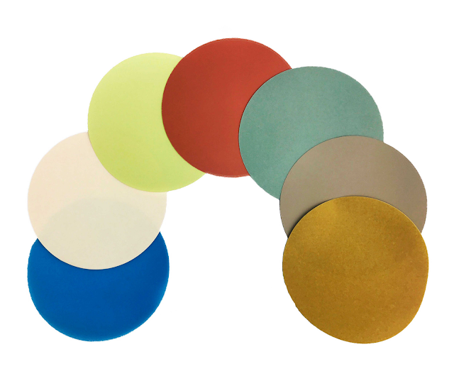
While cleaving often generates a decent surface flatness within a fiber core region of constrained size, it frequently results in significant uneven structures towards the outside border, which can occasionally be upsetting. In a mechanical splice, for fusion splicing, or in a fiber connector, in particular, there may be protrusions that prevent good contact between fibers. You can use fiber polishing pad.


For fibers with relatively high cladding diameters and for some non-standard fiber glasses, which might be particularly brittle, cleaving typically does not perform well.


In this regard, polishing techniques used on fiber ends may yield superior outcomes. In situations with unique needs, such as when constructing a fiber bundle such that all fiber ends very precisely fit a certain plane, polishing may also be necessary.


Unfortunately, polishing typically takes longer than just cleaving. However, taking the effort to carefully polish and review the findings may be time well spent and prevent later on considerably more time-consuming defect hunts. For instance, it is important to reduce the possibility that some of the fiber connections display too high insertion loss or too low return loss if the performance of an optical fiber communications system depends on many different components. The same holds for intricate fiber laser or amplifier configurations. The fiber polishing pad is in demand.