Followers

Wednesday, December 7, 2022

Know About the Fiber Optic Power Meter

A device for measuring the optical power in a light beam, such as a laser beam, is an optical power meter. When receiving a pulse train with a high pulse repetition rate, such as from a Q-switched or mode-locked laser, it often only allows for power measurements with relatively low bandwidth and will, for example, only display the average power. There are further tools, referred to as optical energy meters, for measuring pulse energies.


There are some specialized sensor heads with an integrating sphere that can accept and precisely measure even highly divergent input beams, like those from light-emitting diodes, whereas the majority of power meters are only suitable for light beams with a relatively small beam radius, such as diffuse light.


An optical power meter normally includes a sensor head with the power sensor and optical light source within. This sensor head is usually positioned on a post to receive a horizontal input light beam at a specific height above the optical table. Additional optical attenuators can be added to a sensor head to increase the measuring range; they are especially available for photodiode-based sensors.


The sensor head may be linked to a standalone display device with an analog or digital laser power display. The user is frequently given the option to select from several power ranges and maybe make other adjustments, such as those affecting the laser wavelength or the reaction time. Devices used in the telecom industry may also show power in dBm or decibels of about 1 mW. Some devices offer a digital interface for connecting to a computer or an analog electrical output that delivers a voltage signal proportional to the amount of light received.


It is common for display instruments to be paired with various sensor heads, including sensor heads of various sorts, such as pyroelectric and photodiode-based types.


When using a power meter to measure fiber optic power, attach the meter to the cable. To make sure it doesn't have too much or too little power, compare the meter reading with the system's recommended correct power. Because fiber optic cables operate similarly to electric circuit voltage and require exactly the appropriate amount of power to function effectively, accurate power measurement is crucial. You can buy optical alignment machine online.


Tuesday, November 15, 2022

Get To Know About Stripping Fibers

A fiber gets damaged during stripping with a fiber stripper that won't always break right away. A damaged fiber has a good chance of surviving processing on the manufacturing line intact. There is no way to determine if the fiber has been harmed or not unless the weaker fiber breaks during industrial processing.

A wire stripper with the appropriate settings or a specialist fiber stripper can be used to cut and remove the cable jacket if the fiber is not damaged. Some fiber strippers are more practical because they contain grooves for both the jacket and the fiber. Cutting the aramid fibers requires the use of specialized, ultra-sharp scissors. Since doing so will ruin them and blunt the cutting edge, they shouldn't be utilized to cut anything else. We may now begin to strip the fibers. You must select the instrument you employ for this crucial phase. There are three different kinds of fiber optic stripping tools that are often employed; these are Miller, No-Nik, and Microstrip, respectively.


fiber stripper


Millers are fairly tough and have a wire stripper-like appearance, but using them takes skill. Millers are difficult for left-handed users to handle comfortably because they must hold them at an angle. Due to their lower technical requirements and ability to strip greater lengths of fiber at once, the other two strippers are typically preferred by fusion-splicer operators. To achieve thorough stripping, every tool has to be well cleaned with fiber cleaner.


Fiber Cleaner

It takes a certain amount of tugging to strip the fiber of its buffer layers. With one hand, you grasp the cable or fiber while using the other to grip the stripper. The fiber or cable may be held safely and firmly by wrapping it around a finger a few times.

After removing the colored plastic buffer coating with a 900-micron thickness, there can still be some residue on the fiber. When the stripper did not cut through both layers of coating, there was just the main buffer coating, which has a diameter of 250 microns, left. All of the residues should be eliminated by applying a tight clamp. If you can see portions of the inner buffer, you can strip once again forcefully gripping the stripper to cut through all buffer coats. The fiber cannot be placed into the connection if the buffer coating is not completely removed. You can buy fiber splicer online.


Saturday, October 15, 2022

Peep into the Details of Fiber Optic Probe


There must be at least one excitation and one collecting fiber in the traditional fiber endface probe used to quantify fluorescence. The lighted and probed regions might overlap thanks to a quartz shield that is attached to the distal end of the fibers. The percentage of overlapping rises when the numerical aperture of the fibers and shield thickness are both increased. A greater diameter shield is necessary for a deeper shield.


A fiber optic probe with slanted transmission and receiving fibers is disclosed for detecting dispersed light. These fibers are bundled to produce a bevel at the probe's tip. The transmitting and receiving fibers stored inside the probe's housing, which has a transparent window along the length of its tip, are protected by this. By cutting, polishing, and other methods, the end faces of the fibers are angled such that they lie in a plane that is not parallel to the longitudinal axis of each fiber. The fibers are positioned such that lines normal to the slanted end faces are divergent concerning one another and are held in the probe's tip using epoxy.


The epoxy is tapered such that the transmitting fiber, the epoxy, and the receiving fiber create a bevel of no more than 20 degrees. The epoxy is positioned essentially between the transmitting and receiving fibers. The light cones are directed toward one another by the tilted fiber endface probe, improving the effectiveness of light coupling. The epoxy contains a light absorber, such as carbon black, to lessen the crosstalk between the transmitting and receiving fibers.


The end face of an optical connection or split fiber may be inspected using fiber optic inspection microscopes.


Fiber optic connection termination inspection and fiber patch panel ferrule inspection are two common applications for fiber optic microscopes on the market.


For single-mode fiber applications, fiber scopes may magnify up to 200X or 400X; for multimode applications, a low-cost 100X variety is offered. The latter is frequently a part of tool kits for fiber optic termination.


Video fiber endface microscope is used for ferrule inspection. They consist of a portable LCD device and a compact, lightweight probe with a CCD camera and a long-lasting LED light source. When the probe adapter tip connects to the connection, an LCD is shown that shows tiny particles and end-face damage in crisp, clear detail

Saturday, September 10, 2022

Get to Know About the Fiber Polishing

Preparing optical fiber ends to achieve good mechanical and optical quality is frequently important in fiber optics. For instance, it's required when fibers need to be spliced together or fitted with fiber connectors.


When Is Polishing of Fiber with Fiber Polishing Liquid Necessary?

In many real-world situations, cleaving offers sufficient high quality and is quick and simple to use. However, there are times when cleaving is inappropriate. A few instances include:


Getting a fiber surface that is perfectly perpendicular to the fiber axis may be crucial. Results of fiber cleaving can occasionally be insufficiently dependable in this regard.


The preparation of a fiber surface so that the normal direction accurately forms a certain angle with the fiber axis is much more challenging. Although there are methods for cleaving angles, they often show a significant range in the cleave angle.


While cleaving often generates a decent surface flatness within a fiber core region of constrained size, it frequently results in significant uneven structures towards the outside border, which can occasionally be upsetting. In a mechanical splice, for fusion splicing, or in a fiber connector, in particular, there may be protrusions that prevent good contact between fibers. You can use fiber polishing pad.


For fibers with relatively high cladding diameters and for some non-standard fiber glasses, which might be particularly brittle, cleaving typically does not perform well.


In this regard, polishing techniques used on fiber ends may yield superior outcomes. In situations with unique needs, such as when constructing a fiber bundle such that all fiber ends very precisely fit a certain plane, polishing may also be necessary.


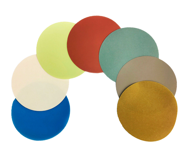
Unfortunately, polishing typically takes longer than just cleaving. However, taking the effort to carefully polish and review the findings may be time well spent and prevent later on considerably more time-consuming defect hunts. For instance, it is important to reduce the possibility that some of the fiber connections display too high insertion loss or too low return loss if the performance of an optical fiber communications system depends on many different components. The same holds for intricate fiber laser or amplifier configurations. The fiber polishing pad is in demand.

Wednesday, August 10, 2022

Absorb the Basics of Fibers Fusion Splicing

The two bare fiber ends are fused by heat in the fusion splicing process with fiber splicer. To be more specific, a little space is left between the fiber ends when they are originally brought into close contact. They are pressed together such that the ends fuse after being heated for a brief period until the surfaces melt. High-voltage electric discharges are frequently used to achieve heating.


Characteristics of Fusion Splicers

Typically, equipment producing high-quality fusion splices will contain the following characteristics:

  • Precision anchoring of the fiber ends is made possible by carefully designed fiber clamps. Micrometer screws are used to accurately adjust at least one clamp.
  • It is further required to spin one of the fibers about its axis when splicing polarization-maintaining fibers or multi-core fibers.
  • Examining the fiber ends' alignment and quality are possible under a microscope. A knob for alternating between two orthogonal directions of view is frequently included. Usually, the fiber cores are also visible.
  • Without touching the fibers, one can clean the surfaces by using a fiber cleaner.


Several unique qualities:

  • A camera picture or the monitoring of the optical power throughput may be used by some splicers to automatically align the fibers. For the latter, a photodetector must be coupled to one fiber end and a light source to the other.
  • The effectiveness of the resultant splice may also be measured by some instruments.
  • While some fusion splicers are designed specifically for use with common telecom fibers, others may work with a wider variety of fibers, such as those with different cladding widths.
  • Some tools simply provide a better level of precision, which is necessary, for example, to splice fibers for space division multiplexing.


Gains from Fusion Splicing

Fusion splicing provides several important benefits over other methods for creating fiber junctions, including the following:

  • Nothing else offers lesser reflections and smaller transition losses.
  • The resultant joints are extremely stable, requiring little alignment maintenance and being impervious to the effects of dust.
  • The only component or material needed is to cover the fiber after splicing.


For outdoor fiber cables, fusion splices are frequently used. In factories, reliable fiber-optic equipment like fiber lasers and amplifiers are also created via fusion splicing. fiber stripper is also a useful tool.

Thursday, July 14, 2022

Get Acquainted With the Facts of Stripping Fibers


Whether installing fiber-optic (FO) cable indoors or outdoors, following a step-by-step process lowers the risk of fiber damage while assuring fiber performance. As we continue to talk about installing FO cables, let's break down how to strip and clean both interior and outdoor FO cables. fiber stripper is a useful tool needed for this.


Without a doubt, using effective stripping methods in your fiber optic cable manufacturing process is essential. What occurs if the fiber is harmed during this manufacturing step? A microscopic nick or scratch in the optical fiber acts as a ticking time bomb. Eventually, if the connection is subjected to stress or temperature cycling, this flaw may cause a fracture to develop. A cable assembly's connection is compromised or lost if a fiber fractures. It may be necessary for your cable assembly house to repair or replace connections in the field, which might be quite expensive for your business. You can buy fiber tool kit online at an affordable price.


The first thing to keep in mind is that each layer must typically be stripped separately when multi-layer cables are being stripped for connecting since they often need to be stripped to various lengths. That is, the layers of the wire above must be peeled one at a time rather than all at once. It is important to take precautions to prevent harm to the layers underlying while removing an outer layer. No matter what kind of stripping equipment you use, make sure to maintain them correctly to keep the cutting blades sharp.


If the fiber is not harmed, a wire stripper with the right settings or a specialized fiber stripper can be used to cut and remove the cable jacket. Some fiber strippers and fiber splicer are more practical because they contain grooves for both the jacket and the fiber. Cutting the aramid fibers requires the use of specialized, ultra-sharp scissors. They should not be used to cut anything else since doing so will destroy them and dull the cutting edge.


Thursday, June 9, 2022

Everything You Need to Know About Fiber Optic Connectors

For high-speed data transmission, optical fiber is a good vehicle but only when the light transmission is efficient across connector assemblies. This translates to the requirement of fiber polishing pad connector end faces to optimize performance. Increasingly, automation of the polishing process is becoming a necessity with the adoption of newer fiber configurations, as well as ever-tightening specifications.


Early physical contact connectors required the spherical forming of their flat end faces as part of the polishing procedure. A four-step process is included under traditional techniques: epoxy removal, ferrule forming, and preliminary and final polishing. For epoxy removal and ferrule forming these steps used aggressive materials that are generally accomplished with diamond polishing films.

Now, the polishing process has developed into a sequence of epoxy removal, followed by rough, intermediate, and final polishing cycles as almost all connectors are manufactured with a pre-radiused end face. One main goal is to avoid excessive disruption of the spherical surface, while still producing a good mating surface. Polished fiber optic connectors then need to conform to a range of performance and geometry-based acceptance criteria.

In two categories the polishing specifications for fiber polishing film connectors are included and they are related to performance and end-face geometry. Back reflection and insertion loss specifications are perhaps the most critical measures of polished end functionality. The latter is the amount of optical power that is lost at the interface between the connectors that usually occur by fiber misalignment, the separation between connections (the air gap), and the finish quality of each connector end. The current standard loss specification is less than 0.5 dB, but less than 0.3 dB is increasingly specified.


Regardless of the connector type, most polishing sequences have now started with aggressive materials, including silicon carbide that removes epoxy and diamond lapping films for beginning and intermediate polishing. These then at the same rate remove both surrounding material and fiber. The last polishing step, however, needs a less aggressive material, such as silicon dioxide, to attack only the fiber. For final fiber polishing liquid using a material that is too aggressive could lead to excessive undercut. The wrong final-polish material can lead to excessive protrusion, then to fiber chipping and cracking during the connector mating process.


Thursday, May 12, 2022

All about Fiber Polisher and Why They Need to Be Preferred

Since the 1990s fiber polishing machine has made big progress. By manual and labor-intensive process, the earliest connector termination job was done and fiber connector polishing was manually done by one single person. However, it needs much higher efficiency due to the development of a fiber-optic network. By adding more operators, the fiber optic patch cord manufacturers generally makeup but still could not catch up with the demand. Fiber connector polishing has met the requirement of high volume, high quality, and consistency until there was the emergence of the current automatic polishing machine.

Fiber Connection Termination is very important for the fiber optic communication system quality. For the whole process of terminating fiber connectors, fiber optic connector polishing is one of the most important steps. It is so because bad polished connectors will increase the insertion loss and back reflection which will make you malfunction.


According to a set of industry-standard and specifications, there is the production of fiber polishing fixture. In a consistent way it can produce large volumes of connectors, and it is even considered to be cost-effective as labor is significantly reduced. The article here is written to help you below is provided certain standards on how to make wise decisions while selecting a perfect fiber polishing machine for your specific requirement

There is a preference for Polishing Machines with Adjustable Pressure

By the combination of the loading pressure and the hardness of the polishing surface, there is the generation of the fiber connector’s finished end-face geometry. The polishing pressure should be adjustable with clearly marked divisions of measurement to optimize the connector end-face.

There is the importance of even the four corner hold-downs. To minimize off-center polishing hold-down fasteners in all four corners of the connector holder evenly distribute film pressure. In case you utilize the center pressure from above, it will allow the possibility of wiggling or vibration of the connector holder. You will increase the vertex offset with this method and it then leads to inconsistent finishes.


You need to consider the polishing pad too. The polishing pad is in conjunction with the four corner hold-downs and it is used to distribute the pressures evenly across the polishing area. Due to the resiliency of the pads, they help in controlling the radius of curvature as the ferrule is pressed into the pad during the polishing process. You need to select the proper fiber polisher according to your need as there are so many pads for different types of connectors.


Wednesday, April 13, 2022

Proper Polishing Fixtures Care for Optical Fiber Polishing Machines

The most critical step to assure high-quality assemblies that meet specifications is perhaps the polishing process in fiber optic cable assembly. That’s why selecting the right optical fiber polishing machine, fiber polishing film, and polishing fixtures are important in meeting your needs. To produce different connector styles, it’s likely that you have several polishing fixtures based on your cable assembly house product offerings.


To your company, the quality of the polishing fixtures is extremely important. To produce a high volume of products with minimal quality issues over the long run, your company will want to maintain these tools considering the high cost of production components and equipment.

For fiber optic polishing, there is a typical fiber polisher. To polish the end faces of fiber optic products, Fiber Optic Polishing Machines are used to minimize signal losses due to scattering. By providing rapid polishing of many different connector styles, Polishing machines can increase productivity.

Proper maintenance of polishing fixtures is essential

With high-precision machining equipment, fiber polishing epoxy fixtures for optical fiber polishing machines are built. Negatively impacting your product quality and polishing process, Fixtures made of aluminum and steel can warp and flex over time. Polishing fixtures made of hardened stainless steel avoid this wear effect on the other hand. However, the risk of rusting is not increased by this as hardened stainless steel contains more iron in the alloy. This is why proper maintenance is very essential.

Onto the polishing fixture with a plastic clamp or latch, the most common fiber optic connectors are locked in addition, which can wear over time if not properly cleaned. The functionality of the polishing machine and product quality are significantly affected by this.


Proper maintenance is very crucial as polishing fixtures are costly. For a long time, you can use your polishing fixtures with daily maintenance with no variation in your fiber optic cable assemblies’ quality level.

For monitoring the quality of your polishing fixture and fiber polishing liquid, an excellent way is to monitor the end-face geometries of polished ferrules. In end-face geometry parameters, any significant deficiencies in the fixture will be reflected.


Tuesday, March 8, 2022

Various Types of Optical Fiber Fusion Splicer


The process of joining two fibers together permanently is Fiber splicing with fusion splicer. Fusion and mechanical splicing are two fiber splicing types.

Two optical fibers are not fused physically in Mechanical splicing, rather inside a sleeve, two fibers are held butt-to-butt with some mechanical mechanism. You will get back reflection and worse insertion loss in mechanical splices as compared to infusion splices. For fiber testing and emergency repairs, Mechanical splicing is mostly used.  

The second type of splicing is called Fusion splicing. By an electric arc, two fibers are welded (fused) together in fusion splicing. As it provides for virtually no back reflection and the lowest insertion loss, Fusion splicing is the most widely used splicing method. The most reliable joint between two fibers is offered by Fusion splicing. Fusion splicing is done with an automatic machine called a fusion splicer.

Fusion splicer

As we said above, the machine used to weld (fuse) two optical fibers together is a fusion splicer. Fusion splicing is the other name for this process. In alignment fixtures, the fiber ends are placed, cleaved, and prepared on the fusion splicer from the fiber tool kit. The fiber ends are brought together after being heated with electrodes and fused at the press of a button.

Fusion splicers are automatic machines that you need to either set the splicing parameters yourself or choose factory recommended settings.

Core alignment

To inspect the two cleaved fibers, Optical fiber core alignment fusion splicers use multiple cameras before fusing. Multiple axis movement of the fibers is allowed by them.


Allowing users to store separate recipes or programs, Core alignment splicers are high-end units where factors such as temperature and splice time can be customized highly. Such high-end fusion splicers visually display the splice after magnifying it, and to line up the fibers, they use active core alignment.

Resulting in a typical splice loss of only 0.02dB, this provides for precise fiber alignment. For all single-mode fiber applications, this level of precision is required and the performance of multimode fiber is also enhanced. Core alignment is usually used by Ribbon splicers. The fiber cleaner is also useful.

Friday, February 11, 2022

Optical Fiber Fusion Splicing and its Benefits

Optical fiber fusion splicing

Optical fiber fusion splicing is a welded joint that is formed between two optical fibers. Compared with another temporary joint such as a mechanical splice fiber splicer is a permanent, low-loss, high-strength joint. In the optical network, optical fiber fusion splices play a crucial role.


Fusion Splicing Process

The main goal is to create a joint with minimum insertion loss yet with mechanical strength and long-term reliability that matches well with the fiber itself.

The ideal process needs to be fast, inexpensive and it should not need expensive equipment. But in reality, among different applications and requirements, the process requires trade-offs. For example, long-term reliability is the most important goal for a fiber stripper and undersea telecommunications.

The Benefits

For interconnecting fibers such as fiber optic connectors and mechanical splicing, there are other approaches too. Compared to these two, fusion splicing has many benefits as explained below.

It provides the lowest insertion loss

It can even withstand extremely high temperature changes

It is one with the Lowest back reflection (optical return loss ORL)

It is very compact

Quite Permanent

It also prevents dust and other contaminants from entering the optical path

Provides Highest mechanical strength

The major steps involved in the process of fusion splicing can be summarized as the following.

  • Optical fiber stripping
  • Fiber cleaving
  • Fiber alignment
  • Fiber welding
  • Insertion loss estimation
  • Pull tension strength testing
  • Splice protection with fusion splice sleeve

What are the Different Splicing Types?

In three types fusion splicing environment and applications can be roughly divided:


  • Field splicing
  • Factory splicing
  • Laboratory splicing

The assembly of undersea fiber cables aboard fiber deployment ships is a very important example of field splicing. One example of factory splicing could be the assembly of fiber optic passive devices such as a WDM. An example of laboratory splicing is performed by researchers by fusion splicing the newest developed fibers so that they can test their compatibility with the existing industry-standard fibers.

Fiber fusion splicing includes various concepts and fiber tool kit from many subjects including mechanical engineering, heat transfer, material science, optical waveguide theory, fluid mechanics, and more.


Monday, January 10, 2022

Get to Know About Polishing of Fiber Optic Connector

Failure of the component or failure of the whole system can be caused by any contamination in the fiber connection. An important component in fiber connection is the Fiber optic connector. As we know, end-surface treatment is required by fiber optic cables for proper light transmission. For almost all glass-based fibers, Polishing and fiber polishing pad is an essential step with diameters and cladding larger than 200 microns. Polishing is also needed by all fiber optic connectors.


Why Polishing is needed by Fiber Optic Connector?

What the connector return loss will be determined by the connector end-face preparation will determine once the fiber optic cable is terminated with a particular connector. Through the light reflected into the light source and the connector in the forward direction by the connector surface, the back reflection is the ratio between the light propagation.

Utilizing narrow linewidth sources such as DFB lasers, minimizing the back reflection is very important in analog and high-speed fiber-optic links, which are prone to mode fluctuations and hopping in their output. To make fiber optic connectors work perfectly, Polishing and fiber polishing film is one of the essential procedures. That’s why we need polishing of fiber optic connector.

Ways of Polishing Fiber Connector

On the fiber connectors, there are several different polish options. Due to the extreme accuracy requirement of today’s fiber connections especially for production polishing is mostly performed by a machine.

For all types of fiber optic connectors, the common machine polishing tools, such as other fiber optic polishing machine kits and fiber optic polishing machines as well as fiber polishing fixtures are used. Fiber optic polishing puck and Polishing paper or some cleanser are needed by the manual fiber optic connector polishing.


Conclusion

As it is an art, Fiber polishing and fiber polishing epoxy is as much a science. Proper polishing of fiber optic polishing is critical for optimum results to a certain extent. However, on your technique or your polishing machine, it also depends. So, for your polishing tool and fiber optic connector, selecting the right company or the right machine is essential.